
Motors utilize the following electro-magnetic principle: a conductor with a current passing through it in the presence of an external magnetic field will experience a force. There is an exceptionally good video in YouTube that demonstrates this principle.
Generators utilize the following electro-magnetic principle: a loop of wire moving through an external magnetic field will have a voltage induced across it. A fine YouTube video that demonstrates this principle can be seen here.
Enough science, let's move on to some basic engineering principles. A brief summary of linear and rotational mechanical power can be reviewed here. The best website tutorial on mechanical power measurement is from Micro Motion Solutions.
Linear Power
To summarize: Work is force times the change in distance
W = f x Δd
Where W is work, f is the force and Δd is the change in distance.If work = force x distance
then power = force x distance/time
then P = f x d/t or
Power = force x rate or
Power = force x speed
Rotational Power
Torque causes objects to spin or rotate.
Torque = force x lever arm
Power is the rate of doing rotational work. Work is the product of torque x swept angle in radians.
W = T x Θ
T is Torque and Θ is swept angle in radians. Power = rotational work/time
Power = T x Θ/t
Since Θ/t = ω angular speed in radians/second, so
Power = T x ω
ω is angular velocity. The unit we use is revolutions per minute (rpm). The conversion of ω (angular velocity) from radians/sec to rev/min:
ωrad/sec = ωrpm x (2π/60)
ωrpm = ωrad/sec x (60/2π)
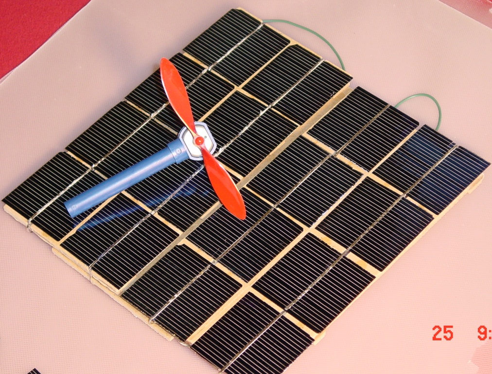
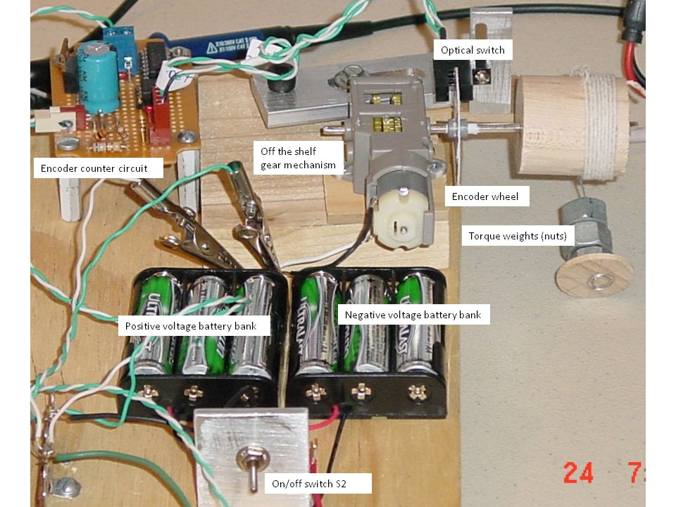
An encoder disk with four slots is mounted on the motor shaft. See the third photo down. The revolution of the motor shaft is measured by counting the slots of an encoder disk as they pass through an optical switch. Click on the ninth photo down and look on the upper right part of the photo to see the encoder disk and the optical switch.
The force applied to the motor shaft is weight in ounces (oz.) and the lever arm distance from the shaft is in inches. Therefore, the units of torque are oz. x in. or oz-in. Therefore, rotational power is defined by:
Power = T oz-in x rpm
When doing power calculations the units involved are important. The oz-in are used because of the scale we use and our optical encoder counts revolutions per second which is easy to convert to rpm. The torque speed product in oz-in x rpm needs to be converted to the SI system of units to produce mechanical power in watts. Torque units of oz-in need to be converted to Newton (N) meter (m) and the speed rpm unit needs to be converted to radians per second (rad/sec). First convert rpm to revs per second (rps) then multiply the rps by 2π to get rad/sec. Or using the oz-in and rpm units we can use the conversion factor 0.00074 to get the product in watts. See example 1. The efficiency E of the energy conversion process is defined by:
E = Pmech / Pelect or Pelect / Pmech
The webpage from Micro Motion Solutions provides a very good description of mechanical power measurement. Except for heat losses due to friction, the conservation of energy principle is proven in the conversion of electrical energy to mechanical energy by accounting for every watt of power.
Measurement of a motor's rotational speed or a generator's rotational speed is made by using a tachometer or by using an optical encoder. The Society of Robots has a good website for how to build and use optical encoders. Details on the construction of our optical encoder and the associated electronics is provided below, for now we'll focus on the torque. A simple direct method to measure torque is explained in the following website: Weight on a string tied to a motor's shaft. Once at this website scroll down to DC Motors for a short tutorial on DC motors. The section Measuring Motor Torque describes a simple way to measure motor torque.
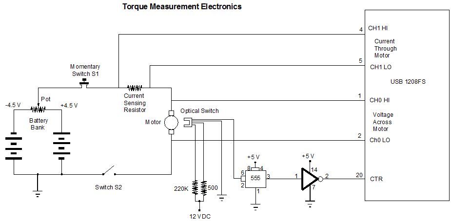
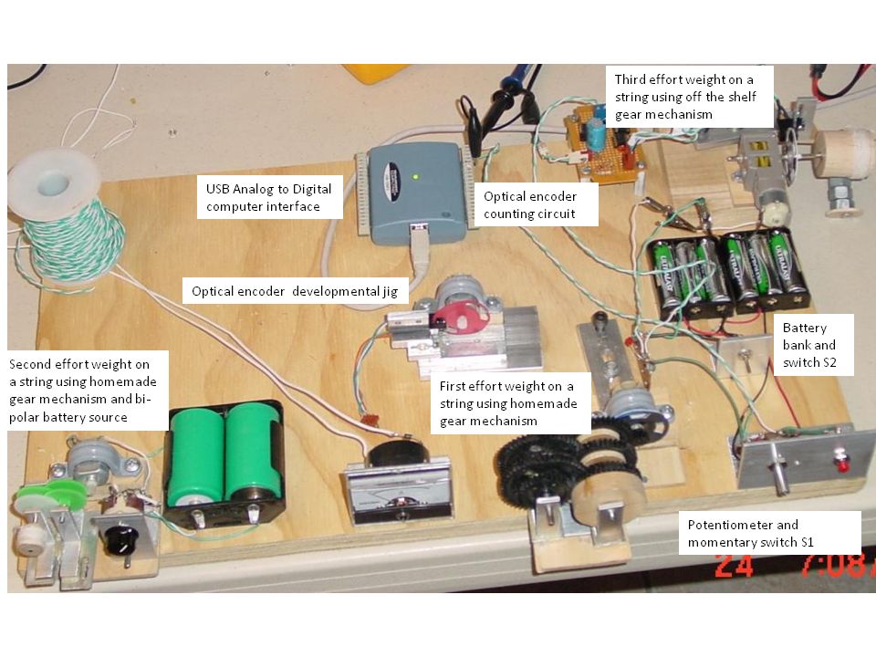
Collecting shaft Speed/Torque measurement values to produce motor analysis graphs requires a bi-polar power supply. A quick alternative is to use batteries connected to a potentiometer to produce a variable bi-polar voltage applied to the motor under test. The graph below shows how a bi-polar voltage is applied to the motor. By rotating the potentiometer shaft the voltage varies in amplitude and varies in polarity. Also notice how the voltage across the motor and the voltage developed across the current sensing resistor are connected to the A/D converter.
To measure the rpm, slots are placed on an encoder disk and mounted to the motor's shaft. The encoder disk has an optical switch placed across the edge of the disk. See the photo towards the end of this page showing the optical switch across the encoder disk. Each time an aperture passes between the optical switch (LED source and detector) a pulse signal is generated and sent to a digital counter circuit. The digital counter counts pulses for 1/2 second. At the end of 1/2 second the number of pulses counted is divided by 4 (4 slots make one revolution) and the count is placed on a computer interface port. Our torque measurement experience was not kind to us. Several experimental motor setups were constructed and tested. Several problems were encountered. Below is a photo of the board used to construct our test jigs.
Placing a string directly on a motor's shaft presents two problems; 1. the diameter of a motor's shafts is too small to make realistic torque calculations, and 2. a small motor's RPM is too high and the torque is way too low to lift a measureable weight. A gear was added to lower the rpm and to increase the torque. Unfortunately, one gear was not enough.
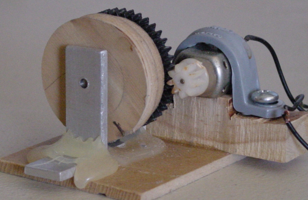
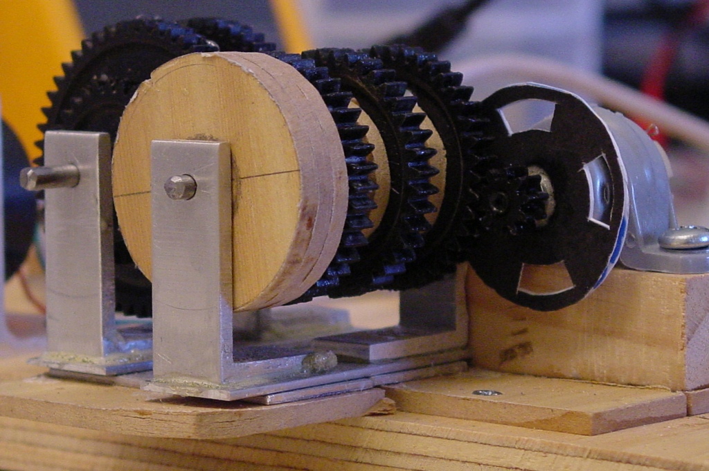
So we tried to improve our homemade gear mechanism by adding more gears. While this setup seemed to decrease the rpm to a workable speed, the transfer of power to the final spool was not smooth. Motor rotation was erratic due to uneven gear friction. See the photo below.
So we switched to thinner gears and this reduced the friction between the gears and the out put gear shaft rotated more smoothly. So more photographs of the third homemade gear mechanism upgrade are shown below.
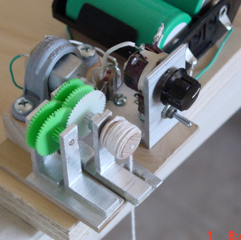
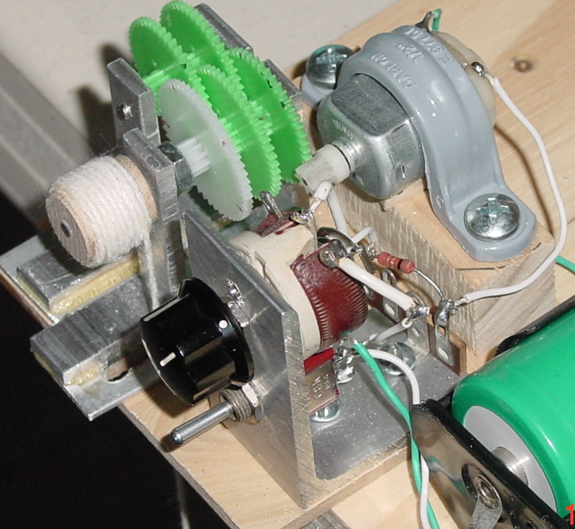
Never the less this combination proved to be too slow, but workable. In the final configuration one gear was removed for a total of 4 meshed gears.
The Society of Robots webpage shows how gears transfer power from a motor to the load. The electrical diagram of the circuit shown below is not a good way to vary the power to a motor. A more effective method is to use a variable output power supply. So we used what we had on hand and this circuit was simple to construct, but difficult to use. The potentiometer is used to vary the current to the motor. Note the resistor behind the potentiometer in the photograph above.
While this is theoretically a good way to measure current flow through a circuit, it is not the best way. The better technique is to use a current sensing IC and will be addressed at a later time. We continue with the description of this circuit. Note in the diagram below the current sensing resistor is used to measure the current flow through the circuit.
Ok, so setting up a gear mechanism is not trivial. So we purchased one and it worked better. See the gear mechanism by clicking on the third photo below. Notice the wooden spool and the encoder wheel are mounted to the gear shaft in the immediate photo below. While the motor's shaft rotates at a high rpm (above 800 rpm), the gear shaft rotates at a lower rpm (about 4 rpm).
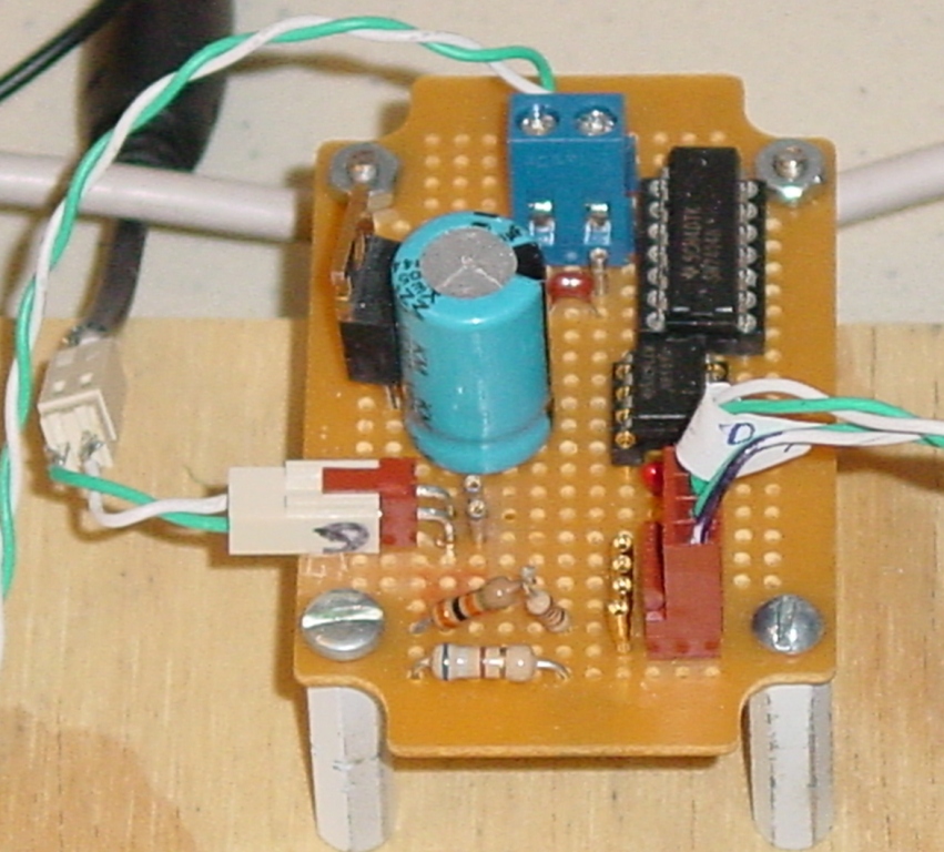
Close up of the optical encoder/counter circuit photo is shown below. This circuit receives electrical pulses from the optical encoder mounted on the motor shaft. This signal enters at the connector on the lower right of the board. A 555 timing IC is used to buffer the signal. The 7414 Schmitt trigger is used to shape and clean the signal before connecting it through the blue connector on the top center of the board. The green and white wires take the conditioned pulses to the USB 1208FS counter. Refer to the diagram of this circuit above labeled "Torque Measurement Electronics".
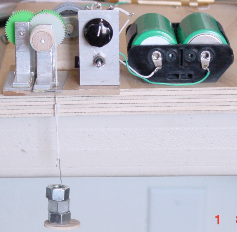
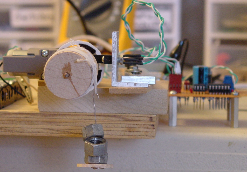
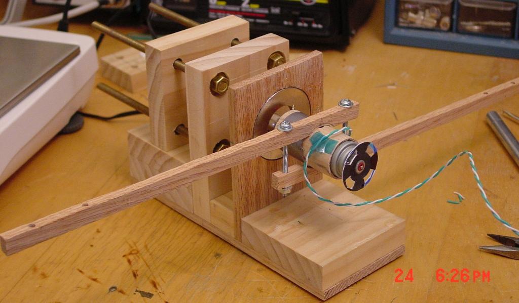
A view of the latest effort to make the weight on a string method work is shown below. The three nuts on the right of this photo are the weight (force) applied to the wooden spool by a string. The radius of the spool in inches times the weight of the nuts in ounces equals the torque (oz. in.) on the motor's shaft. On this same shaft is the encoder disk which is used with the optical switch to count the number of shaft revolutions. Only problem with this setup is that the encoder disk and the spool are not mounted directly on the motor shaft. They are mounted on a gear shaft. In this case the motor's shaft is inaccessible. Further more the motor's shaft rotates too fast for the weight on a string method to work, so we used this gear box to reduce the spool rotation. Please review this website for an explanation of how a motor's rotational speed and torque are transformed using a gear mechanism.
The following formula helps to exchange the torque and speed parameters through a gear mechanism:
OTorque * OVelocity = NTorque * NVelocity
where OTorque=Old Torque, OVelocity=Old Velocity, NTorque=New Torque, NVelocity=New Velocity
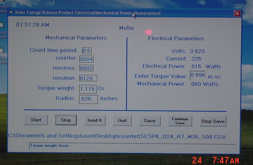
A gearbox with an overall gear ratio of 203.7 to 1 is used here. That is, for one rotation of the spool, the motor shaft rotates 203.7 times. From the photo above note the spool shaft also contains the encoder disk, so we only measure the spool rotation. Knowing the gearbox ratio we know that the motor rotates 203.7 times faster than the spool does. So if the spool rotates at 120 rpm, then the motor rotates at (120*203.7=24444) 24444 rpm. So now we know two values of the torque speed formula. The third value, the torque is known because it is the weight we put on the string. For example suppose 5 nuts weigh 1.115 ounces and the spool radius is 0.625 inches. The torque is then (1.115 oz * 0.625 in.) 0.697 in. oz.. Using the formula above we have
OTorque * 24444 rpm = 0.697 in. oz. * 120 rpm or
OTorque = (0.697 in. oz. * 120 rpm)/24444 rpm = .00342 in. oz.
Or using gear ratios to obtain the motor's torque:
.697 in. oz./203.7 = 0.00342 in. oz.
Ah, same value. Gear efficiency also comes into play here. Assume the gearbox gears are spur gears, so the efficiency per gear mesh is 90%. The gearbox has 4 sets of gears meshed. So the torque applied to the motor shaft through the 8 gears is damped by .9 x .9 x .9 x .9 = 0.656 or 65.6%. There fore the total torque applied to the motor shaft is 0.00342 in. oz. x .656 = 0.00225 in. oz.
Now in order to convert mechanical units in.oz. and rpm to watts use the following conversion factor: 0.00074. Where did this conversion factor come from? From here. There fore the motor's output mechanical power is 0.00225 in. oz. x 24444 rpm x 0.00074 = 0.0406 watts.
These formulas and methods will be described in a step by step data acquisition instruction set. Now to move on to another torque measurement method.
The Prony brake torque measurement method. How to use a Prony brake can be reviewed here. This is a modified use of the Prony brake method. Recall Newton's laws of motion that for every action there exists an opposite and equal re action. The photo below shows how the setup works. As power is applied to the motor's armature and starts to accelerate, the stator (motor case) will accelerate in the opposite direction with equal force. This force is measured by the Gram scale to the left. The torque equals the force measured by the scale times the distance from the end of the piece of wood to the motors shaft. The product of the torque and the shaft rpm defines the motor's mechanical energy.
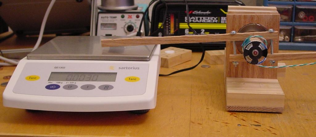
The photo below shows a perspective view of how the motor is balanced by magnetic bearing. If after further testing this method proves feasible, construction details will be provided.
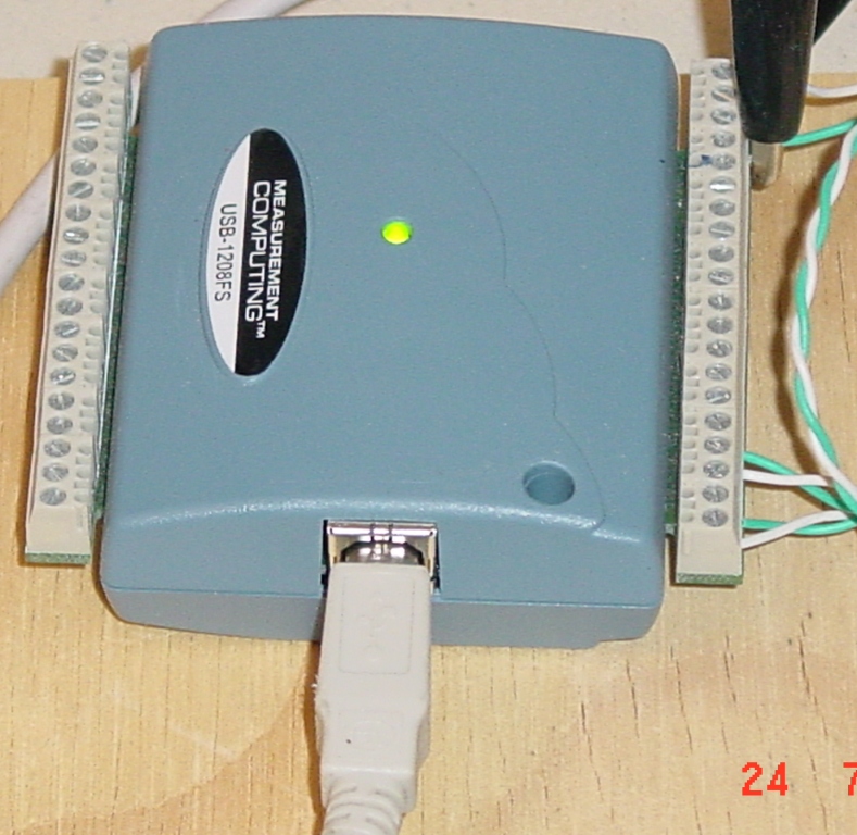
Motor voltage, current and the motor rpm count is interfaced to the computer via a USB 1208FS analog to digital converter from Measurement Computing. Measurement Computing's USB computer interface is one of many options to interface analog signals into your computer and at $189.00 is not inexpensive. We will research cost effective methods of digitizing and interfacing electrical signals into your computer.
The product of the voltage across the motor and the current through it represents the electrical power applied to the motor. The Torque of the motor's shaft times the shafts rpm represents the motor's mechanical power. A program then reads the voltage, current and rpm count and the operator enters the weight on the spool and the radius of the spool and uses these values to compute electrical power and mechanical power. See the program display screen below.
Step by step instructions on how to characterize a motor's or generator's efficiency will be described soon. Motor performance data will be collected using these setups and this program to produce motor analysis graphs.