
Power Measurement
This kit demonstrates how to make three types of power measurements:
Optical power measurement is important because the primary source of power is the sun's optical radiant energy. Electrical power measurement is important because electricity, a secondary energy source, has not only been important in our daily lives, it is the most efficient form of power delivery. Mechanical power measurement is important because it is the last stage of how our lives are comforted. Electric motors are now and will be in the 21st century the most efficient means of drive for all forms of transportation.
How to Measure Irradiant (Optical) Power (General Overview)
The sun's radiant energy is a subset of the electro magnetic energy spectrum including optical energy. Under clear skies, a little over 1000 watts per square meter of solar power irradiates the earth. That's how much solar power is available to us per square meter of earth. How much of this energy is converted to electricity depends on a number of factors: Size of solar array; Atmospheric conditions; And solar cell conversion efficiencies. Then there's the time of day matter; how do we store solar energy during the day and use it at night?
An effective device used to measure solar radiant energy is the pyranometer. The Responsivity of pyranometers to solar energy is flat across the solar spectrum. The Ideal pyranometer measures the suns total energy, that is it measures the energy contained in all the wavelengths of the sun's radiation spectrum, not just the visible. The only problems with pyranometers are the sensing speed and the expense, so we will use a simpler and less expensive detector material. Silicon. The Silicon photovoltaic (PV) cell measures only a small portion of the sun's total spectrum. Yet Silicon is the material most used in the manufacture of solar cells. We will use a PV cell to measure solar radiant energy. Please click on the following link for the details on how to measure solar power (optical power). Optical irradiance measurement
How to Measure Electrical Power
But first visit this website for a review of basic solar energy electricity. Although we work only with DC power, here is a website that briefly describes AC power.
Measurement of electrical power requires a volt meter to measure the voltage across the load and a current meter to measure the current flowing through the load. Among other types of instruments used to measure power, the digital multi-meter (DMM) can measure voltage, current and resistance. Current has two modes of operation: Alternating Current (AC) and Direct Current (DC). We will only be working with DC voltages and currents. Go to Using a Multi-meter website to see how a multi-meter is used.
Voltage is the pressure that causes a charge to flow around a circuit. Charge flow is designated as current. Wire is used to carry the current from the source to the load. A circuit is the circular path electrons (charge) flow through. The circuit below consists of either a battery or a solar cell, the connecting wire, the motor on the right, and the return wire to the source. The battery or solar cell is the source and the motor is the load. The wire is the conduit used for the electron charge to flow from the source to the load.
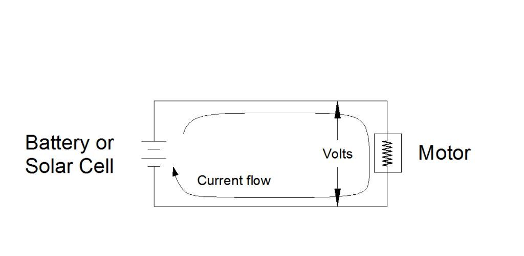
Notice the battery or solar cell is connected to the motor by wire and a wire connects the other side of the motor to the bottom side of the battery or solar cell. This defines the circuit. The source provides voltage (force) and current (flow). The load produces the work desired and provides resistance to the current flow and is represented in a circuit by a resistor. An important volt/current/resistance relationship is Ohm's Law:
V = I x R
Where V=voltage, I=current, and R=resistance. Knowing the value of any two variables results in the value of the third variable.
I = V / R and R = V / I
The power delivered to a component is given by the product of the voltage and the current.
P = V x I
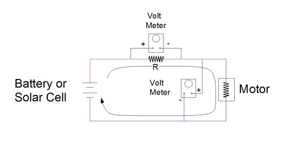
Where P = power in watts, V = voltage (also known as tension or pressure) in volts, I = current in amperes or amps. The basic unit for voltage is the volt; the basic unit for current is the ampere or amp; and the basic unit for power is the watt. One way to make a power measurement is by measuring the voltage across the load and the current that flows thru the load. To measure voltage set a DMM to measure voltage and place the leads across the motor as shown in the diagram below. To measure current set the DMM to measure current and place the DMM in series between the source and the load (motor) as shown below.
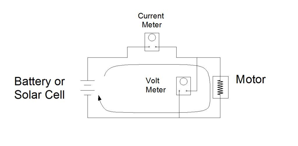
Note the current meter is inline on the input wire to the load (motor) and the volt meter is across the load. Another way of saying this is the current meter is in series with the source and motor and the volt meter is parallel to the source and the motor.
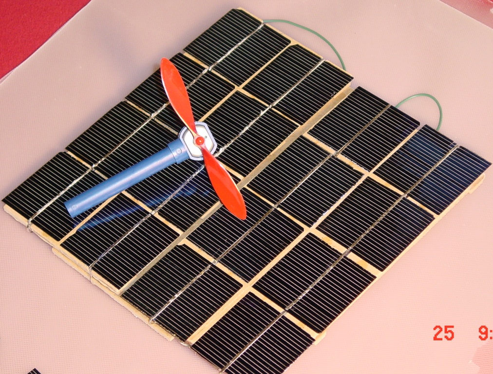
Below is a photo section of the of the Solar Energy Science Project Kit showing a close up of the motor connection.
In this top view of the kit, the motor on the left receives electrical power from either the solar cells or the storage batteries. The motor on the right functions as a generator and produces power for the windmill motor on the far right. To measure the voltage across the motor place the positive DMM lead on the blue connector and the negative lead on the red connector. Note the two resistors, on each of the red leads of the motor and the generator, are connected in parallel to each other. These are two 0.1 Ohm 1% resistors parallel to each other, which makes the combined resistance 0.05 Ohms. Low resistance is used to measure the current through a motor. The two parallel resistors in the photo is the same as the .05 ohm resistor (R) in the diagram below. The value of resistors in parallel is computed with the following equation:
1/RT = 1/R1 + 1/R2 + ....
RT = (R1 x R2)/(R1 + R2)
There fore RT = (0.1 X 0.1)/(0.1 + 0.1) = 0.05 Ohms. This resistance is used to measure the current through the motor and this is how: A resistance of 0.05 Ohm presents low resistance to current flow, but there is a voltage drop across it. So by measuring the voltage drop across the resistance R (.05 Ohms)the current through it will be known using: I = V/R. And this is the same current that flows through the motor. Once the DC voltage and Current have been measured the power is computed by multiplying these values.
P = V x I = V2 / R
Electric Flow Thru a More Complicated Circuit
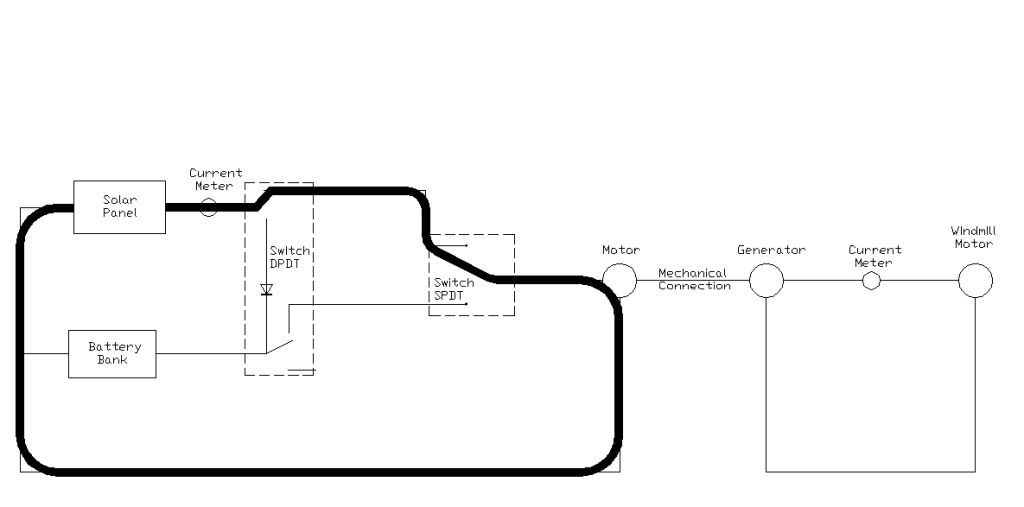
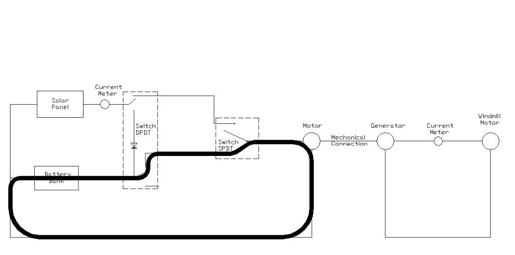
Electricity flows from the electrical source, through wires, electrical components and back to the source in circular fashion. That is the current flows in a loop and returns to the source. Below is a diagram of the solar energy science project kit. Depending how the switches are set, current will flow in a circular loop. In this case electricity flows through one of four current loops. The DPDT switch on the left of the diagram is the function switch. With it you can choose to send solar panel current to the motor or to charge the batteries. The SPDT switch located at the center of the diagram (source select switch) is used to select solar cell current or storage battery current to run the motor.
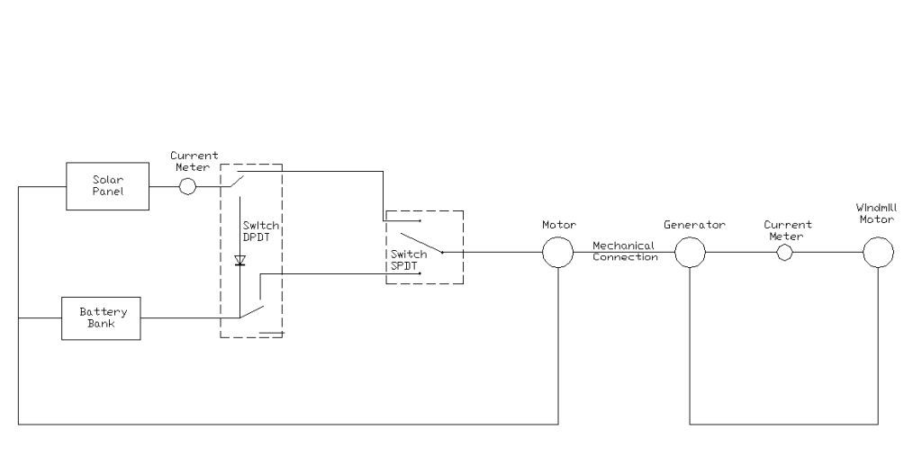
With the function switch set to "current flow to motor" position and the source select switch set to "solar panel" mode the current will flow from the solar panel, through the amp meter, through the switches, thru the motor and back to the solar panel.
With the function switch remaining in the "current flow to motor" position, and the source select switch set to "batter power", the current will flow out from the positive side of the battery bank, flow through the switches, through the motor and return to the negative side of the battery bank.
Setting the function switch to "charge battery" mode directs the current from the positive side of the solar panel, through the amp meter, through the function switch, through the battery bank and returns to the negative side of the solar panel.
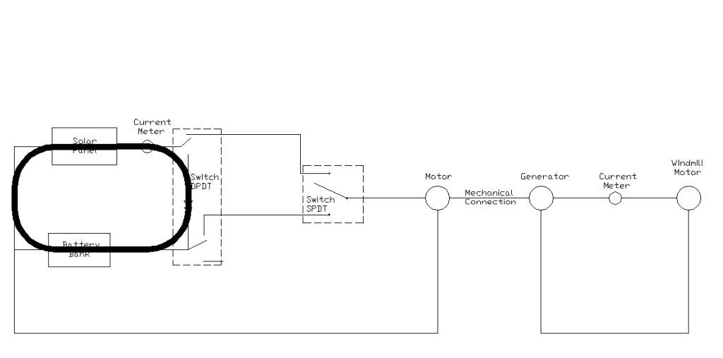
Of course no current flows from the motor to the generator, but mechanical energy does "flow" through the chain and sprocket to the generator. On the generator side of the kit, the current flow starts at the generator, flows through the amp meter, then flows through the fan motor and returns to the generator.
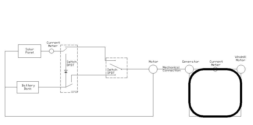
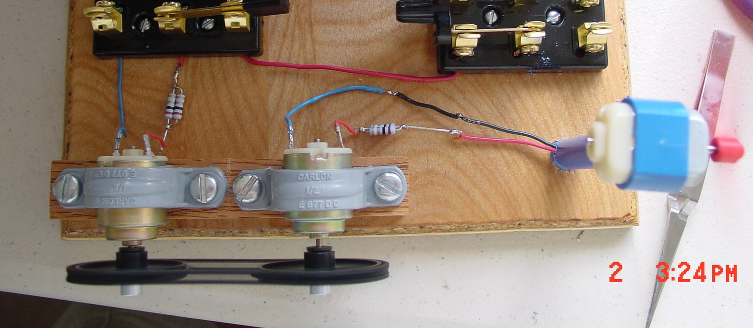
Ok, now try to identify the circuit flow on the actual kit. First follow the wire from the solar panels to the amp meter, then to the switches, then to the motor, then thru the wire back to the solar panels. Note how mechanical power flow does not require a return path to the source as does electric power flow.
Storage Batteries
Up to this point we've discussed how to measure electrical power into a motor and out of a generator. The power to and from a battery is measured in a similar fashion; that is by measuring the voltage across the battery and the current flowing out from or into the battery. The power from the battery is the product of the voltage time the current. Recall the relationship between electric power and energy. Electric power is the rate at which electric energy is transferred within an electric circuit. Also refresh your memory at this website. The energy capacity of a battery is specified in milli-amp hours for small batteries or Amp-hours for large batteries. That is the number of milli-amps the battery can provide for one hour. A battery rated at 2500 milli-Amp Hours will deliver 2500 milli-Amps for one hour, or 1250 milli-Amps for two hours, or 625 milli-Amps for 4 hours.
Batteries are normally charged at 1/10 the battery capacity (C/10). So, if the battery capacity is 2500 milli-Amp Hours, the safe charge rate is 250 milli-Amps for 10 hours (250 milli-Amps x 10 Hours = 2500 milli-Amp Hours). Due to battery leakage and other factors, the total energy recovered will be less than what was put in. So in reality, less than 2500 milli-Amp Hours of energy are available for use from this battery.
How to Measure Mechanical Power (General Overview)
A motor's mechanical output power or a generator's mechanical input power measurement requires two distinct types of parameters to be measured; the rpm (revolutions per minute) of the motor shaft and the torque in inch pounds or Newton meters applied by the shaft or applied to the shaft.
1. The RPM is a measure of how fast the shaft rotates. In general, a shaft rotates many times per second, but the standard measurement unit is shaft revolutions per minute or RPM. We will use an optical encoder to make this measurement. An optical encoder will be constructed and interfaced to a computer to calculate and record RPM.
2. The torque can be measured in many ways. We will explore the simplest and least expensive techniques. The weight on a string method and the Prony brake method will be investigated. Torque is defined as the force (weight) times the distance where it is applied to the point of rotation (radius of circle). The current through the motor increases as the weight it lifts is increased. Current, torque and rpm will be measured and used to construct motor analysis graphs.
Detail of how to measure mechanical power using actual devices and techniques.