Solar Energy Science Project Kit
Detailed Description
Energy Flow
The point of this project is to demonstrate how solar energy arriving at the solar cells is converted to electricity and how this electric energy is converted to mechanical energy and how mechanical energy is converted to electrical energy. Energy flow starts at the solar cells where photons are converted to electrons, this electrical energy (electron flow) flows to the electric motor through metallic wires where it (electric energy) is converted to mechanical energy. Finally the mechanical energy flows to the generator via chain and sprocket where it (mechanical energy) is converted to electrical energy.
Electricity is routed via wires and switches to run a motor or to charge batteries. An analog meter displays the current flow from solar cell to the motor or to storage batteries. When the function switch is set to route the electrical energy to the motor, the motor runs and converts the electrical energy to mechanical energy. The motor is connected with a chain and sprocket to a generator. The electric motor's mechanical energy output is transferred to the generator where it converts the mechanical energy to electrical energy. The generated electrical energy is used to power a windmill looking fan. As we all know, a windmill uses air flow to produce electricity. This kit uses a motor with a propeller blade to simulate a windmill, but it in fact operates as a fan. A second analog meter displays the electric current flow produce by the generator to run the fan.
With the function switch set to charge battery mode, the electricity from the solar cells is used to charge batteries. The analog meter displays the current flow that charges the batteries. after the batteries are charged, this electrical energy is available to run the motor when there is no sun light available to produce electricity. This is accomplished with a second switch that selects electric power from either the solar panels or the batteries.
This demonstrates how green electric energy can be stored and later harnessed to do work such as running an automobile, cool a home or run motors in a factory. Click here to see the various current flows within the circuits of this kit.
The kit is divided into five function groups:
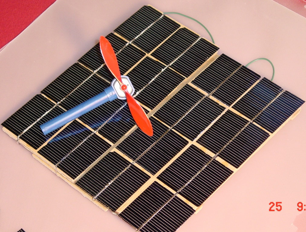
1. Power source (Solar cell array). Solar panels convert solar energy to electricity that either operate a DC motor, or chargeds batteries to store this energy.
2. Power storage (Batteries). Power collected from the sun can be stored for later use. In this case batteries are used as the storage medium. Two D size rechargeable battery cells are used to store energy.
3. Switching function (Electric switches). A double pole, double throw (DPDT) function switch selects the option to run a motor, or to charge batteries. A single pole, double throw (SPDT) switch selects the power source; solar cells or batteries.
4. Energy conversion (Motor/Generator assembly). A chain and sprocket set connects the motor's shaft to the generator's shaft. This demonstrates the conversion of electrical energy to mechanical energy (motor), then the conversion from mechanical energy back to electrical energy (generator).
5. Work demonstration (Windmill kit). A generator produces electricity to run a third motor that turns a propeller made to look like a working windmill. The work produced in this case is the rotation of propeller blades in order to move air.
To enhance the learning process, understanding and interest, the following ideas were incorporated:
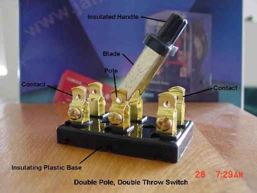 1. Knife switches are used to aid the visualization of the switching process and to enhance the appearance of the model
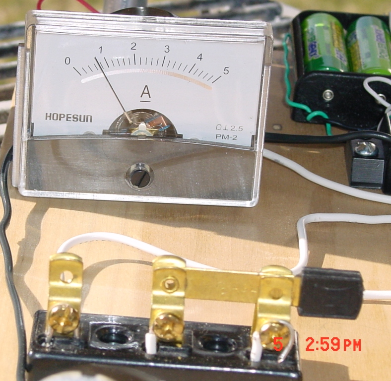 2. Two current meters are used to display current flow. The meter in the picture above is a 5 amp meter to monitor the current flowing out from the solar panels. Another similar current meter monitors the current flowing out from the generator to the fan.
3. The generator (motor closest to blue pole) produces electricity that powers another motor. This illustrates the fact that this generator produces electricity that performs work (Moving air)
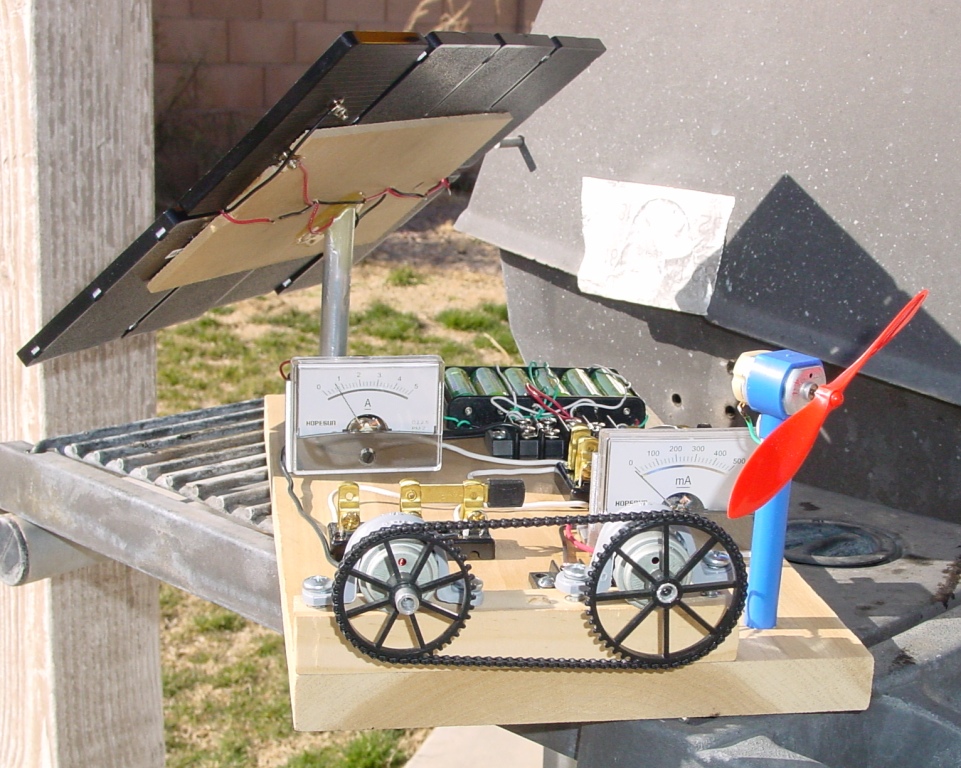 4. Two analog current meters display current flow. The meter nearest to the solar panel displays the amount of current produced by the solar panel. The meter nearest the fan (mounted on blue pole) displays the amount of current flowing from the generator to the fan.
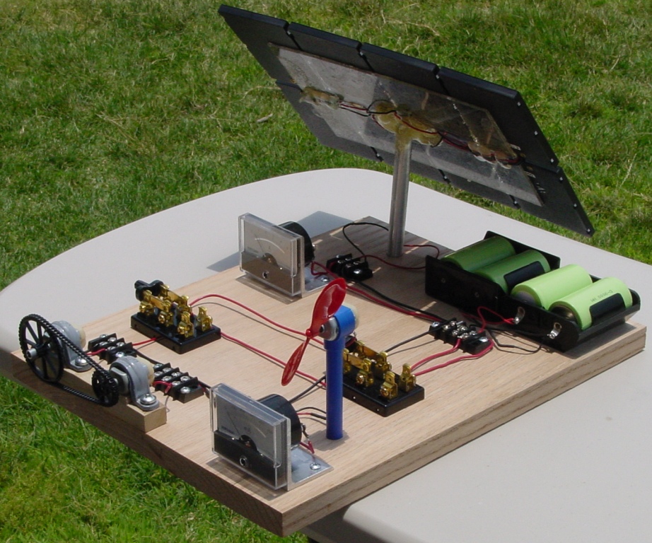 Photo of a larger layout. Courtesy of Mr. Toto
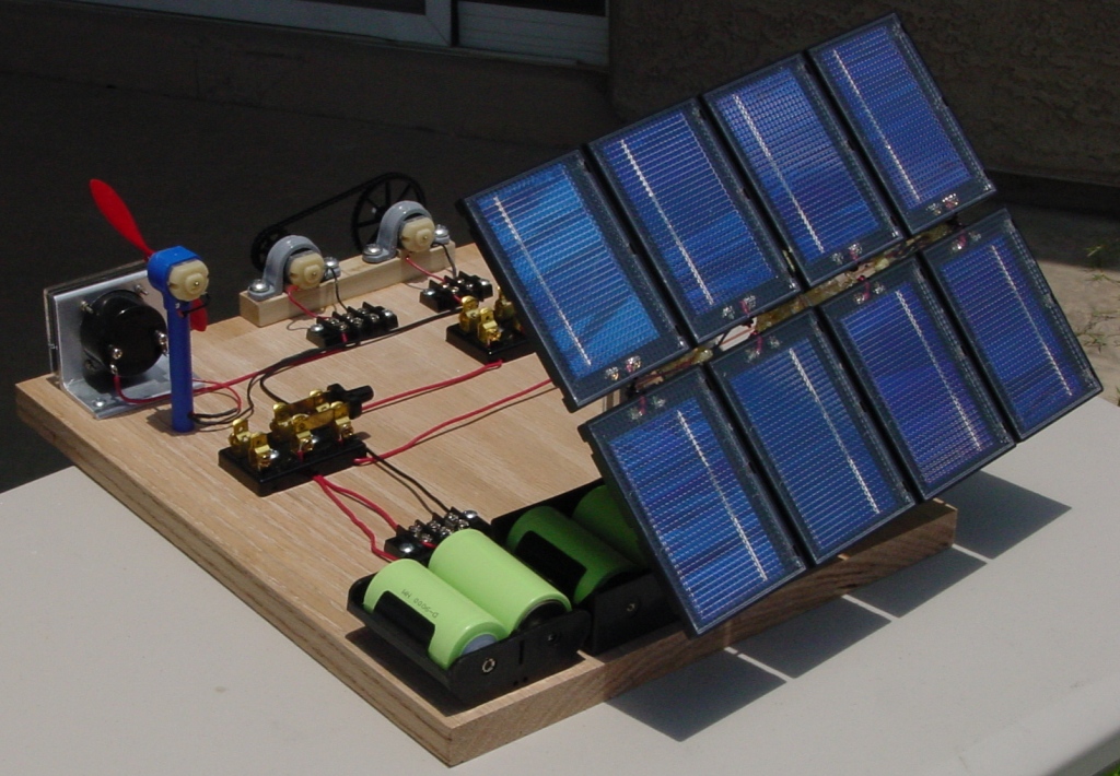
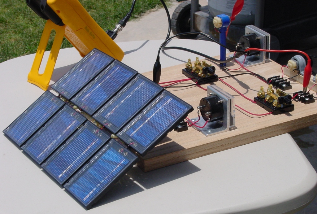 Array down to capture the rays from the sun at a higher elevation
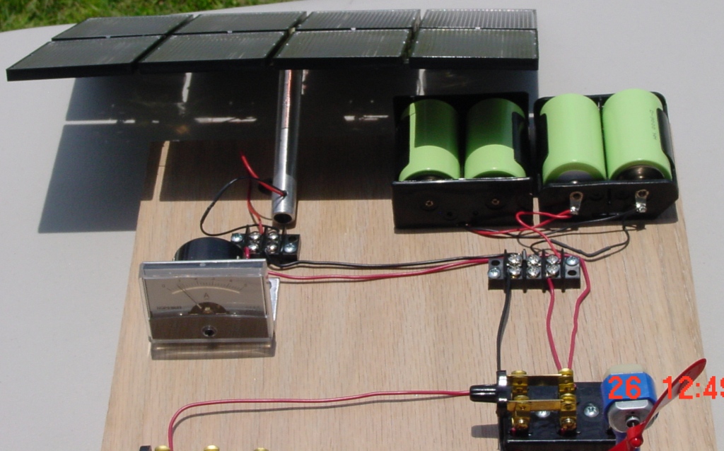 Front view of solar science kit with array down
The following items are required to assemble a kit
- Digital Voltmeter
- Soldering Iron and solder
- Standard slot screwdriver
- Wire cutter and stripper
- Small hand drill or Dremel tool
- Epoxy, Epoxy Putty or a Hot Melt Glue Gun
- Time and Patience
The following hardware is required:
- Three permanent magnet DC motors (One motor works as a generator)
- Eight 0.45 Volts @ 0.8 Amps solar cells
- One single pole, double throw knife switch
- One double pole, double throw knife switch
- Wire and wood screws
- An 12.5 in. x 8 in. x 0.75 in. birch plywood base
- One 0.75 in. x 0.75 in. x 3 in. wooden motor mount base
- Wooden solar cell mounting supports
- Six AA size Nickel-Metal Hydride batteries
- Six battery holders that hold 6 AA size rechargeable batteries
- One 0.25 in. diameter x 3 in. long windmill mounting pole
- One windmill blade
- One IN914 diodes
- Two 2 position terminal
- One 3 position terminal
- One 4 position terminal
- Two sprockets (Material: DuPont Delrin 500)
- One drive chain
- One 5 Amp analog current meter
- One 500 milli-Amp analog current meter
- One 5.5 in. x 7 in. x .093 in. wooden solar panel holder
For indoors demonstration of the Solar Energy Science Project, two 90 Watts Halogen flood lamps can be used to make this kit work. These two Halogen lamps are 24 inches away from the solar cell array. Learn why is takes two 90 watts flood lamps to make solar cells work indoors. Learn how the radiant energy from the sun is different than the light from light bulbs.
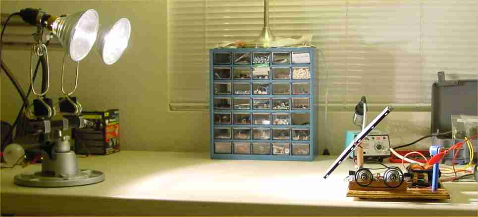
Disclaimer: This is a solar energy science kit, as such it is designed to work from solar energy. It may not work using home lighting. The energy content of a 100 Watt light bulb is not sufficient to operate this kit. It may operate using the appropriate Halogen flood lamps, but care should be taken when working with 120 Volt AC line power. As the picture above shows, two 90 Watt Halogen flood lamps can make this kit work. The flood lamps are 24 inches away from the solar cell array. Ninety Watt flood lamps generate a great amount of heat; care must be taken not to place the flood lamps too close to the array or the heat could melt the solar cells. We are not responsible for any accident or death resulting from attempts to make this project work with line power.
Normally NiMH batteries of any size are used as the storage medium. Green AA size Nickel Zinc (NiZn) batteries can also be used as a storage medium. C and D size NiZn batteries are not available to the public at this time. Two advantages with NiZn batteries:
1. 30% more voltage in the same package size, overcoming the problem previous rechargeables had of only delivering 1.2 V versus the 1.5 V of single use cells.
2. The battery contents of NiZn are non toxic, which makes them even safer in case of accidents. And most importantly, NiZn is reportedly the "most recyclable rechargeable chemistry on the market". More information on NiZn batteries can be found here .
You can see this completed kit running on YouTube here.

