Optical Power Measurement
The measurement of solar energy is similar to the measurement of optical (light) energy. Therefore, to measure solar energy one must understand optical energy. International Light has a good handbook on Light Measurement.
"Light is just one portion of the electromagnetic waves propagating through space. The electromagnetic spectrum covers an extremely broad range, from radio waves with wavelengths of a meter or more, down to x-rays with wavelengths of less than a billionth of a meter. Optical radiation lies between radio waves and x-rays on the spectrum, exhibiting a unique mix of ray, wave, and quantum properties." International Light Handbook. Solar radiation is a subset of all electromagnetic radiation. NASA Goddard Space Flight Center has a good website that explains what the electromagnetic radiation spectrum is.
The sun's optical radiation contains a wide spectrum of wavelengths.
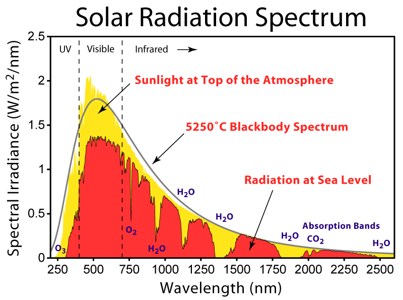
Credit Wikipedia for the above image of the sun's spectrum.
The Solar Radiation Spectrum above shows the sun's Electromagnetic Radiation power content. The horizontal axis represents the wavelength distribution of the sun's power starting at 250 nanometer (nm), ending at 2500 nm. Actually the sun's radiant power extends far beyond 2500 nm. The vertical axis on the left represents the power content in Watts per meter squared per nm. Radiance, the radiation exiting from a source, has the same units as irradiance, radiation arriving on an object. So the image above shows the Watts per square meter per wavelength that arrives on the earth. The spectral output from the sun can be simulated by a blackbody profile according to the Planck function. The sun's output spectrum deviates from the smooth blackbody spectrum due to absorption by elements in the sun's atmosphere. The first thing to note is the shape of the energy profile that shows the energy distribution. The peak wavelength occurs at a little over 500 nm, with the power dropping off towards the longer wavelengths (2500 nm)and shorter wavelengths (100 nm). Each wavelength contains a certain amount of power.
The second thing to notice in this image is that there is more sunlight power at the top of the earth's atmosphere (yellow) than there is at sea level (orange). The atmosphere absorbs much of this radiation. Due to the absorbing gases present in our atmosphere gaps exist in the radiation spectrum that reach sea level. Starting at the short wavelengths Ozone (O3) absorbs energy at wavelengths to about 350 nm. Note the sharp spike of missing energy from wavelengths at about 780 nm due to absorption from Oxygen (O2) gas. A large gaps exists around 900 nm, 1300 to 1400 nm and 1800 to 1900nm due to water vapor absorption in the atmosphere.
Semiconductor physics. "In semiconductors and insulators, electrons are confined to a number of bands of energy, and forbidden from other regions. The term "band gap" refers to the energy difference between the top of the valence band and the bottom of the conduction band. Electrons are able to jump from one band to another. However, in order for an electron to jump from a valence band to a conduction band, it requires a specific minimum amount of energy for the transition. The required energy differs with different materials. Electrons can gain enough energy to jump to the conduction band by absorbing either a phonon (heat) or a photon(light)". Credit Wikipedia.
To measure the sun's energy the appropriate detector should be used. A number of parameters, called performance figures of merit, are used to determine how well within a specific application a detector works . One of these figures of merit is the Responsivity. Detectors respond only to certain wavelengths of electromagnetic radiation. A detector's Responsivity is defined by the incident radiant power that results in electric current flowing out of the detector per wavelength. That is to say the Responsivity of a detector is the amount of current out of the detector per watt of radiant power into the detector's active area.
R(responsivity) = I (amperes)/L (watts)
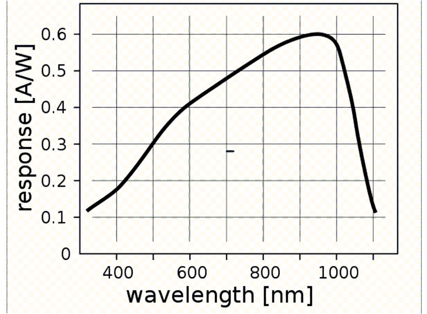
Below is the responsivity spectral profile of a typical Silicon detector. Note the peak response of this type detector is around 1000 nm, away from the sun's peak radiant power around 500 nm.
Other detector figures of merit are the Noise Equivalent Power (NEP), the Detectivity, the Linearity and the Quantum Efficiency. These parameters are important, but will not be discussed, except for the Quantum Efficiency, with our solar application. There are many fine websites that expand on detector performance.
Ok, so Silicon detectors responds only to solar radiation energy at wavelengths between 350 and 1100 nm and is most efficient around 1100 nm. Different detector materials have a different wavelength response to solar radiation. A pyranometer is a device used to measure solar radiation. A thermocouple pyranometer has a "flat" response to the sun's energy. Different pyranometers made from different materials will have a different responsivity. A TruTrack pyranometer sensor from Intech Instruments LTD. has the following responsivity:
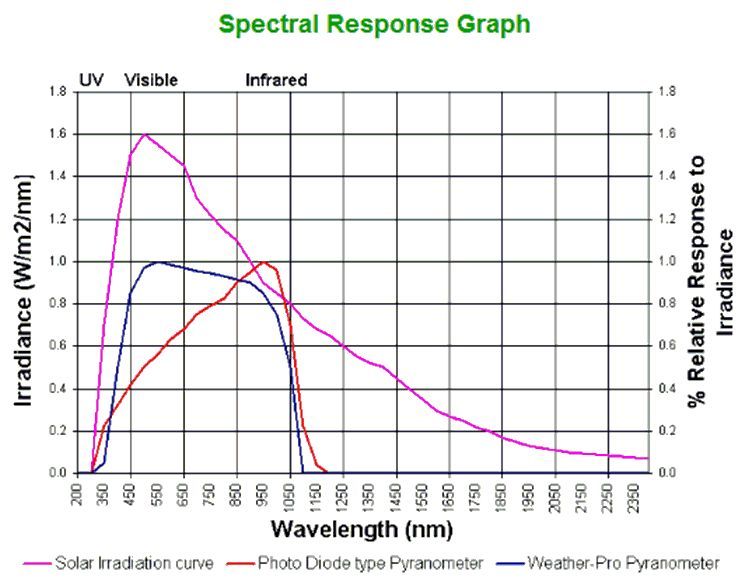
This pyranometer's response is flatter that the Silicon photo diode pyranometer. There are flatter response pyranometers made of thermopile, but thermopile has a slower response time. Max Planck developed the law that predicts a blackbody's radiation output as a function of temperature. To measure the total power in the sun's radiation that reaches the earth, the power contribution of each wavelength from 100 nm to about 10,000 nm are integrated together. By knowing the sun's temperature (~6000 degrees C) and using the Planck Blackbody function equation, the total amount of solar radiation can be closely estimated. Basically, by knowing the total power reaching the earth per square meter (~1000 watts/m2) and knowing a detector's Responsivity (Amps/watts), the sun's irradiant power can be converted to an electrical signal that represents the sun's watts per squared meter . There are other factors to be aware of when measuring solar power, such as detector orientation to the sun, the humidity and the amount of cloud cover present.
Then there is the spatial attribute of light. For example, is radiant energy collimated, diverging or is it converging? Well, by the time the sun's energy reaches the earth, it's optical energy is collimated. As opposed to the light from a light bulb which is diverging. The energy from collimated light does not diminish with distance, where as the energy from a diverging light source is inversely proportional to the square of the distance. So, because an incandescent light bulb's light energy diverges, less visible light reaches an object the further it is from the bulb. What about converging light? Converging light occurs when working with lenses or curved mirrors. These optics are used to focus light to light sensors or imagers.
The sun's higher temperature of 5800 degrees Kelvin contains mostly visible energy and a incandescent lamp's temperature of about 2800 degrees Kelvin contains mostly thermal energy. This is seen in the Electro Magnetic Spectrum of light bulbs. Page 8 of John H. Scofield's The Solar Spectrum shows the spectral content of an incandescent light bulb is mostly IR heat. Professor John Scofield's 9 pages from Chapter 3 of his book "The Solar Spectrum" is very informative on solar radiation and optical radiation in general.
One good light measurement detector is the 731 Smart Detector from Cirrus Photonics. With a $1060.00 price tag this is prohibitably expensive for many people. A little research may locate a Silicon detector and the appropriate optical filters to produce a more cost effective light meter.
Homemade Visible Radiometer
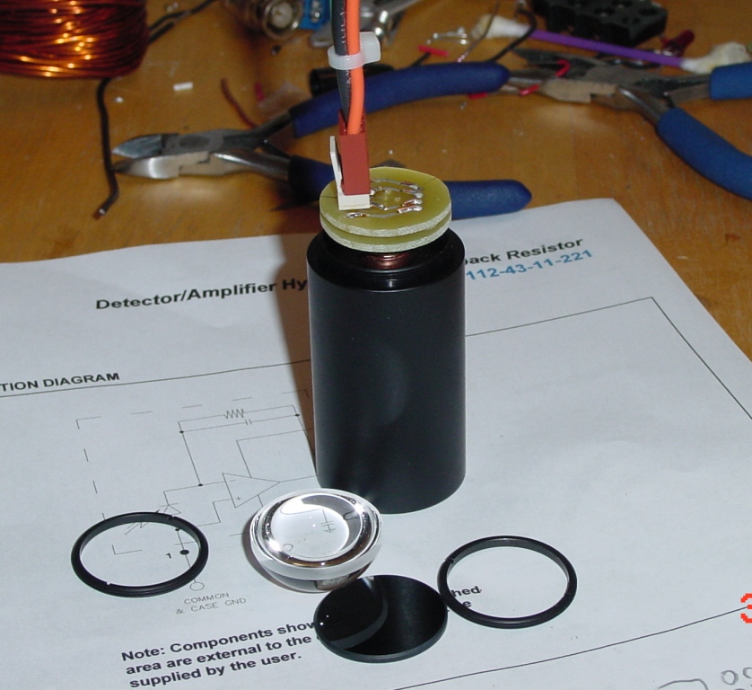
A good candidate for a light measurement sensor is the Advanced Photonix Inc., amplifier hybrid model number SD-112-43-11-221. An absorbing neutral density filter may be required to keep the detector from saturating (See diagram below).
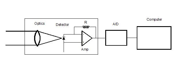
The block diagram of the light measurement system is shown below. Critical to this setup is the calibration of the detector/amplifier hybrid so that realistic radiation measurements can be made. With the photodiode operating in photovoltaic mode, the current is the critical parameter to measure. The transimpedance amplifier is the circuit to use with a photodiode. This configuration provides 0 bias across the photodiode and the output current is a virtual short to ground. The transimpedance amplifier causes the photocurrent to flow through the feedback resistor which creates a voltage, V = IR. Click here to see this detector/amplifier hybrid data sheet. Only light containing wavelengths between 300 nm and 1100 nm can be detected and measured.
Calibration of a detector can be done by one of two ways: 1. Use a calibrated light source of known radiant output in watts/cm2 so that it fills the detector's active area. Then tweak the detector's electronics so the known watts/cm2 is displayed. 2. Use a calibrated detector to measure the watts/cm2 of a light source of unknown output. Once the irradiant watts/cm2 is measured and known, replace the calibrated detector with the detector under test. Now irradiate the detector under test and tweak it's electronics so the output matches the calibrated detector's output. Traceable calibrated sources and detectors are expensive to own. Perhaps you can borrow a calibrated optical power meter or use the one at work or have your detector calibrated by the NIST calibration services.
National Renewable Energy Laboratory (NREL): "Calibration involves comparing an instrument output signal with a measurement standard traceable to a recognized standard to identify and eliminate deviations in accuracy. Calibration therefore allows researchers to compare data from different sources, be confident in those data, and produce better estimates of the uncertainty of a measuring instrument, system, or process. Calibration traceability is the ability of a measurement to be related to national or international standards through an unbroken chain of comparisons with stated uncertainties. Traceability also ensures data quality and is an important part of NREL's calibration activities."
The photo of a homemade visible radiometer along with its 12 volt power supply is shown below. The radiometer barrel has a neutral density filter installed.
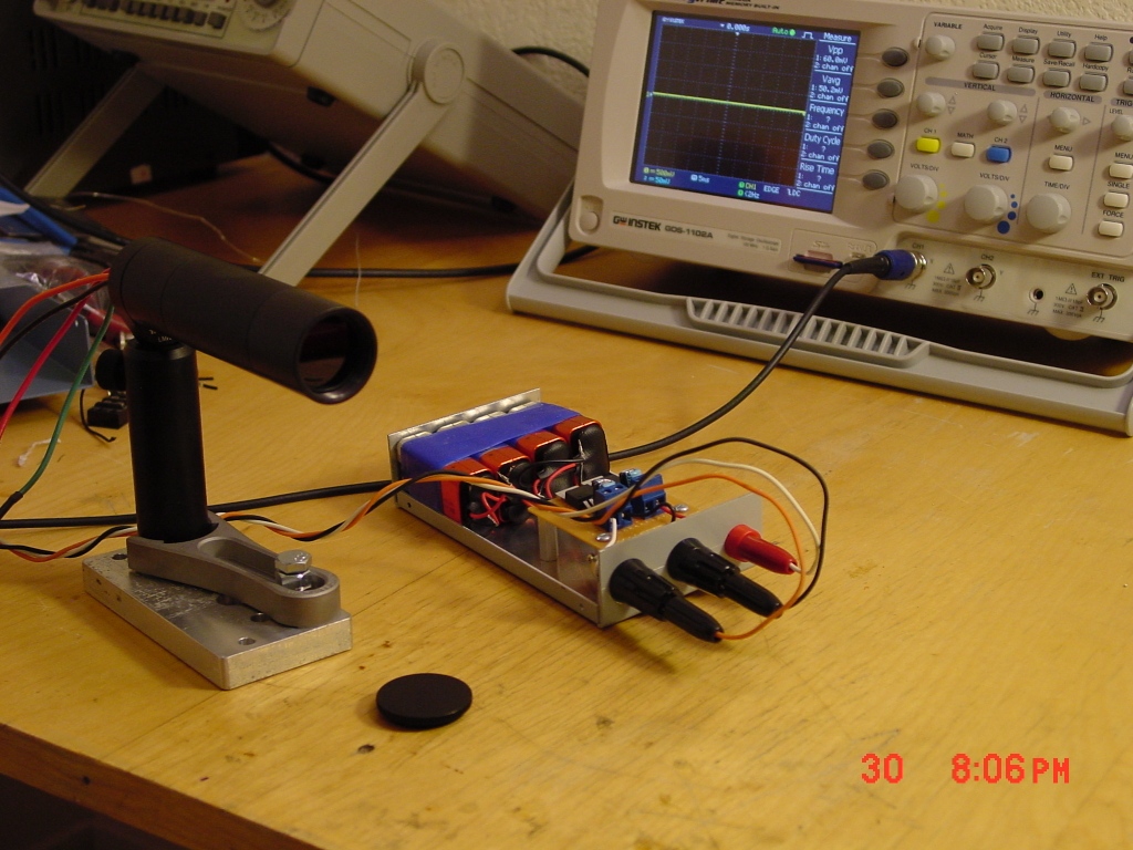
The cost for parts of this homemade light sensor is around $355.00 (See the parts list below). The conversion of radiant energy to an electrical signal starts with the detector transfer function. In this case: 4.9 x 10⁷ Volts/Watt (Ambient Temp = 23 C, Voltage Supply = +/- 12 VDC) represents a high gain detector. The detector transfer function sensitivity (4.9 x 10⁷ V/W) is provided by the manufacturer. Depending on the radiant power being measured, this detector's high sensitivity may require an attenuation filter on the order of Neutral Density (ND) 2 or ND3 be used.
Silicon Radiometer Parts List
| Unit | Total | ||||
| Description | Part No. | Qty | Price | Price | |
| 1. | SM1 Lens Tube, 1" Long, One Rtng Ring Included | SM1L10 | 1 | $14.25 | $14.25 |
| 2. | SM1 Lens Tube, 2" Long, One Rtng Ring Included | SM1L2 | 1 | $16.50 | $16.50 |
| 3. | SM1 Retaining Ring for Ø1" Lens Tubes & Mnts | SM1RR | 3 | $4.50 | $13.50 |
| 4. | SM1 Series end Cap for Machining | SM1CP2M | 1 | $17.50 | $17.50 |
| 5. | Unmounted dia. 25 mm Absptve NDFilterOD1 | NE10B | 1 | $32.00 | $32.00 |
| 6. | Unmounted dia. 25 mm Absptve ND FilterOD2 | NE02B | 1 | $32.00 | $32.00 |
| 7. | SM1 Series Mount for 5.6 mm 9 mm Lasers | S1LM9 | 1 | $26.80 | $26.80 |
| 8. | SM1CP1 End cap internal threads | SM1CP1 | 1 | $16.00 | $16.00 |
| 9. | LMR1 Lens mount for 1" optics | LMR1 | 1 | $15.70 | $15.70 |
| 10. | PH3E Pedestal Post Holder L=3.19 | PH3E | 1 | $23.50 | $23.50 |
| 11. | CF175 Large Clamping Fork 1.75" Cntrbr slot | CF175 | 1 | $9.90 | $9.90 |
| 12. | TR2 1/2" x 2" Post | TR2 | 1 | $5.19 | $5.19 |
| Subtotal | $222.84 |
| |||||||||||||||||||||||||||||||||||||||||||||||||||||||||||||||||||
Solar Radiation Measurement
Solar cells are plentiful and cheap, so a low cost solar radiation sensor can be constructed from Silicon solar cells for tens of dollars. An excellent website which details the intricacies of making a Silicon sensor capable of measuring the sun's radiation can be viewed here. This website will serve as the basis for the construction of our low cost solar sensor.
Silicon sensors can operate in either current mode or voltage mode. A Silicon solar cell can be used as an irradiance sensor, because the short circuit current is proportional to the sun's radiation. A low resistance shunt placed across the PV cell terminals is used to measure the voltage developed across it. An transimpedance amplifier is then used to amplify the small voltage developed across the low resistance shunt.
An transimpedance amplifier can be expensive to purchase and thorny to implement. So if a low value resistor is used, be prepared to use a sensitive voltage measurement meter or analog to digital converter. Current sensing circuits will be developed here.
Never the less, a good reason to use a Silicon solar cell to measure solar irradiance is because that is precisely what the Silicon solar cells respond to.
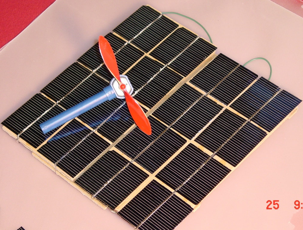
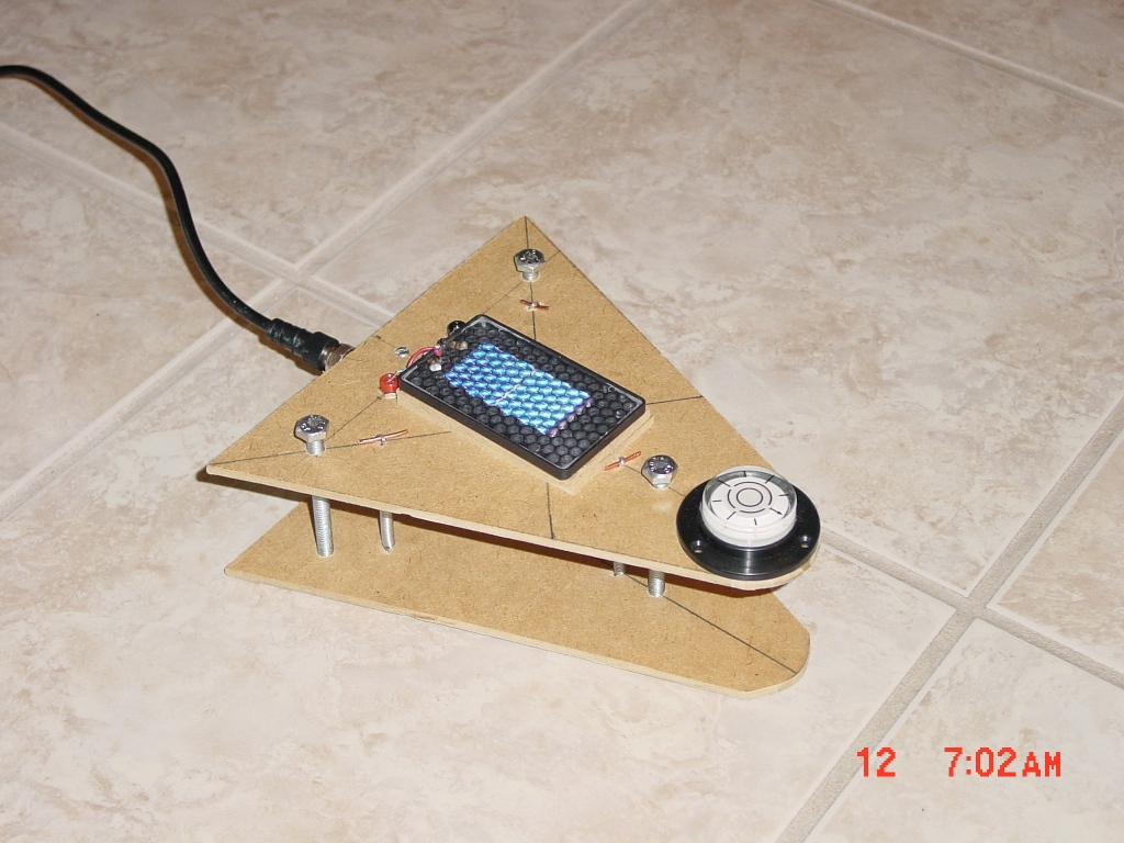
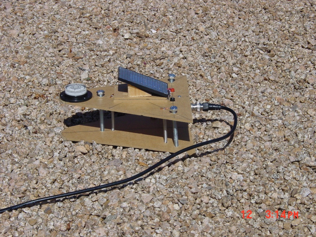
Top front view of the homemade solar sensor.
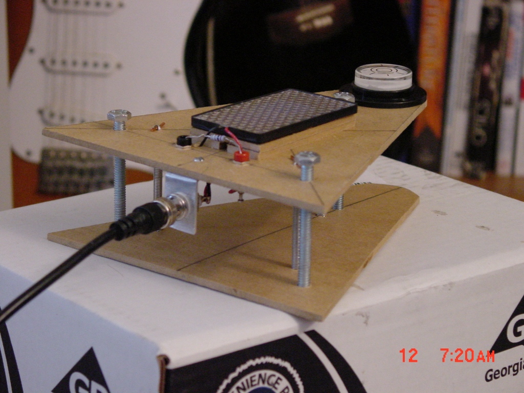
Rear view showing the solar cell and bubble level on top and an aluminum bracket supporting a BNC connector. Output current of this cell passes through the 0.1 Ohm resistor to generate the voltage that is measured by an Analog to Digital Converter.
Solar radiation sensor measuring sun's energy. Top base is leveled with bubble level and wedge is used to orient cell perpendicular to solar rays. Once the top base is horizontal with the earth, a wedge angle corresponding to the latitude of your location on earth is placed underneath the sensor.
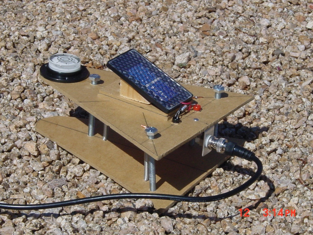
The sensor base can be placed on a rotary base to follow the sun across the sky. A rotary base to use will be shown at a later date.
So what exactly does the output voltage from this sensor mean? Well it is supposed to represent the solar radiation in Watts/m 2. Go to the website and scroll down to Making the Meter for calibration instructions.